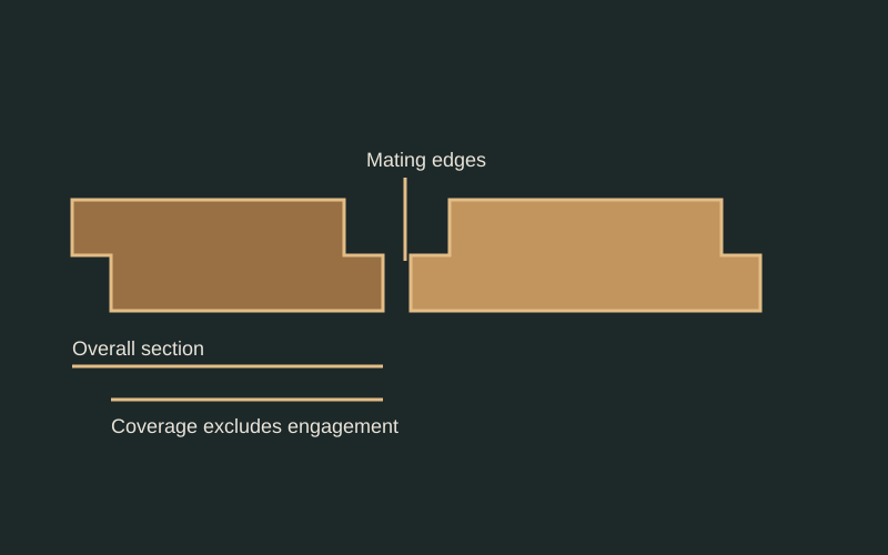
- The complete section includes its mating edge.
- Tongue engagement or lap changes the installed coverage.
- These family sections have no verified machining dimensions; obtain the supplied drawing.
Name the overlapping parts
Draw the two opposing edge rabbets and identify which portion overlaps the adjacent board. Label the intended outward face and top edge where orientation matters. Shiplap is often used casually in design conversations; the drawing must show whether the requested look actually comes from an overlapping section, a separate spacer, or another joint.
Define the reveal separately
The visible line between installed boards is not automatically the same as the hidden overlap. Record both on the assembly sketch and show the reference points used to measure them. If the appearance is being copied from an image, ask for a physical sample or section rather than scaling the reveal from a perspective photograph.
Connect coverage to assembly
Measure or obtain the finished board width, then identify how the intended overlap affects installed coverage. Keep those values in separate schedule columns. Review a short assembly against the drawing before translating room or wall dimensions into quantities. Borders, openings, and cut lengths belong in the takeoff rather than being concealed in a guessed coverage number.
Resolve the exposure detail
Describe the proposed orientation and exposure to the person responsible for the wall or ceiling assembly. An overlapping edge should not be treated as a complete water-control strategy. Record the separate decisions for drainage, backing, terminations, and attachment in the project documentation. USDA's broader wood guidance supplies context, not approval for a particular cladding configuration.
Check corners and changes of direction
Review inside corners, outside corners, starts, stops, and transitions using the same section that was approved for the field. A face mockup can reveal whether a return exposes a rabbet or creates an unintended shadow line. Resolve those details before ordering special trim, and label any distinct trim profile so it cannot be substituted for field boards.
Practical checklist
- Show opposing rabbets and the exposed face.
- State reveal and overlap as separate features.
- Use installed coverage in the takeoff.
- Review corners and terminations before ordering.
Worked example
Hypothetical example: a designer approves a narrow shadow line, while the draft order lists only overall board width. A two-board sample establishes the intended installed relationship, and the order references that assembly instead of an ambiguous style name.
Limits of this guide
This is a profile documentation workflow, not a weather-resistance specification. Do not infer a universal overlap, fastening location, or exposure rating from the word shiplap or from unrelated softwood product standards.
Continue the decision
Keep face width and installed coverage separate
Build a profile submittal that closes the missing details
Match a replacement profile using a retained sample
Profile explorer