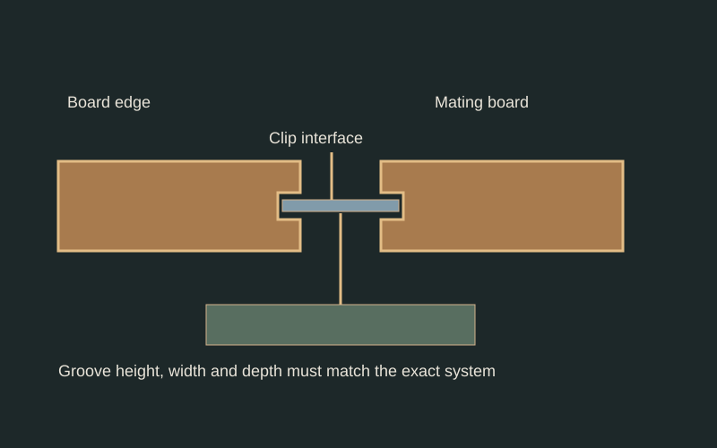
- The groove receives a system-specific clip interface.
- Groove geometry and clip geometry must be checked together.
- Clip, screw and support are schematic, not a compatible product or approved installation.
Identify what the groove does
An edge groove may be intended to receive a clip, mate with another component, or serve a different purpose. State the purpose on the drawing. For hidden fastening, record the exact clip product and revision alongside the board profile. A groove that looks familiar should not be accepted as evidence that any available clip will fit.
Measure from a consistent face
Use the intended walking or visible face as the datum. Record groove position, opening, depth, and remaining material above and below it. Note whether one or both edges are grooved and whether the geometry continues through board ends. Photograph the measuring position so another reviewer can reproduce it without guessing which surface was used.
Inspect more than one point
Compare several positions along the sample and several boards from the shipment. Keep individual readings rather than averaging away a location where the clip cannot seat. Mark damaged, compressed, or torn groove areas separately from apparently intact machining. Record whether a measurement came from unfinished stock, coated material, or an existing weathered board.
Review the whole attachment
Ask the system documentation to identify the board, clip, screw, supporting material, and installation method together. USDA's fastening guidance emphasizes that joint behavior depends on its components and wood properties. A clip sliding into a groove checks only one interface; it does not establish withdrawal resistance, movement accommodation, or compatibility with the support.
Use a small assembly as a communication tool
Prepare a labeled sample assembly following the specified instructions. Photograph clip seating before it is concealed and note the resulting face relationship. If parts bind or leave unexplained play, keep the samples unchanged and seek a written resolution. Do not deepen a groove, bend a clip, or substitute screws merely to finish the demonstration.
Practical checklist
- Identify clip and screw products precisely.
- Measure groove features from the exposed face.
- Record variation and local damage separately.
- Retain the approved system documentation with the order.
Worked example
Hypothetical example: a spare clip enters a replacement board's groove but cannot seat as shown in the installation detail. The buyer records the mismatch and requests the approved pairing instead of treating partial engagement as compatibility.
Limits of this guide
No groove dimensions or clip capacities are inferred here. A sample assembly cannot validate a proprietary connection or an altered profile. Obtain application-specific acceptance from the responsible designer and system documentation.
Continue the decision
Measure a hardwood profile so another person can verify it
Build a profile submittal that closes the missing details
Match a replacement profile using a retained sample
Profile explorer